DIY TKL AEKII keyboard (Extra Thick with to Cs)
by mertkaya on Mar.01, 2023, under DIY stuff
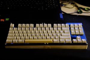
I am proudly announcing that my long waited mechanical keyboard project is finally done.
I had the urge to build a keyboard from scratch for a while after seeing all the custom keyboard making videos on Youtube. The problem is, that keyboard stuff is way to expensive. So I never really got to making a custom one. Instead I looked for vintage keyboards and restoring them for daily use. Because it is much more affordable and build quality is often better than what is on the market.
This is the first one I totally designed and build myself:
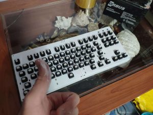
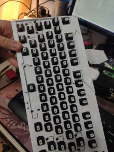
The build of this keyboard I will soon explain started with my “keyboard dealer” sending me an image of what he thought might took my interest. It was a road kill of an keyboard as it can be seen from this image:
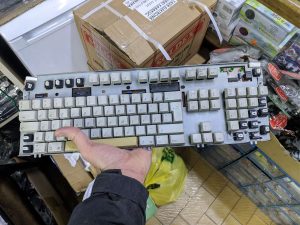
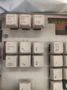
Turkish F keyboard keycaps are interesting and all but it is missing some critical key caps like Left Control and Shift which prevented me from using them. I ended up removing all of the switches. The switches are dampened white Alps. They have little plastic bumpers in them to dampen the clicking. 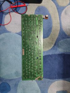
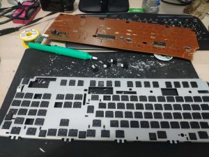
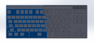
I first still had the idea that I could fix and use the original PCB even though it looked like one chunk of it was eaten. I did fix all of the traces but ended up not using the PCB at the end because it was simply incompatible with other key caps I wanted to use on this keyboard. I traded the Turkish key caps for a full US ANSI set from another Apple AEKII keyboard with a fellow keyboard enjoyer from USA. Unfortunately both the plate and PCB is incompatible with ISO layout which brings out the reason I got a 3D printer to print myself a new plate. Plate is generated from a site called ai03 plate generator. I decided to not use number keys on this keyboard hence the name TKL, ten keyless keyboard. This makes it smaller and easier to hand wire. Also saves pins of the micro controller.
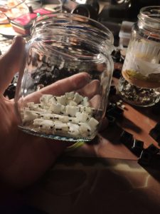
The switches themselfs were taken apart manually to put them through a process called wax modding where the white stems of the switches get mixed with hot water and tea candle wax. This leaves a thin layer of wax on the switches and act like a lubricant. This removes binding of the switches and make them feel smoother in general. After the tedious process of cleaning every part if the switches and putting them together I had a jar full of clean switches. I determined that 93 of them were functioning perfectly. I had about 10 switches that did not register perfectly. They could be fixed but I wanted to use the best ones since I was going to have extra from excluding the num pad.
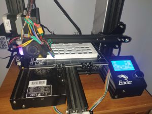
After securing the switches the difficult part was remaining. Drawing the actually keyboard. Thankfully the community had some really helpful people that guided the process. I had a lot of problems with drawing this in Solidworks and it ended up as a good learning experience. Meanwhile I was also messing with thee 3D printer I acquired second hand and it was broken from the day 2 and I had to work on it quite a lot
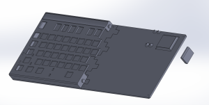
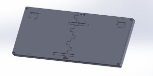
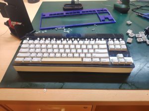
I ended up making a front plate to hide the switches. The end model looked like in the bottom image. It was made from two sections so that i would fit the bed of most 3D printers. The parts that switches I harvested clip in was the most difficult to get right because the tolerances were too tight. If it was a tiny bit too small they would end up not fitting. This was solved by changing the horizontal expansion setting of the 3D printer to compensate for its inaccuracies. 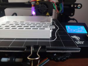
I glued the two important halves that were the main pieces of the keyboard and gave it some sanding and used some of the art putty I had, to fill the gaps in model planes to fill the gaps in pieces for this keyboard. After that It took a lot of sanding and re-applying the putty to get it better but as it can be seen from the final photo of the thing it ended up imperfect. I also used some model paint because the color of white putty and white PLA did not match.
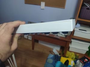
At this point I realized that my 3D printed keyboard was too thick. The thing that caused this was basically Solidworks doing Solidworks things.
I used the .dxf file I got from ai03 plate generator to make the keyboard around it. But somehow Solidworks decided to scale the thing up by 1.48X and I never realized this while drawing the keyboard since I never had a reference to compare how big it was. Fortunately solutions as simple, scaling the whole thing by that exact amount. This caused a lot off dimensions to get messed up and I had to adjust things like micro USB port, micro controller holder etc.
It turned out I had to print thee bottom piece as well since screw holes were too large for M2 screws to screw in. Using brass inserts would be much better in this case since screwing directly into PLA causes some of the threads to become lose after few screw cycles. But I was too tired from messing in CAD software and printing these pieces took way too long for me to bother printing them again.
My keyboard was pretty much done in mechanical wise but I had to wait for key caps to arrive and it was time to do the wiring.
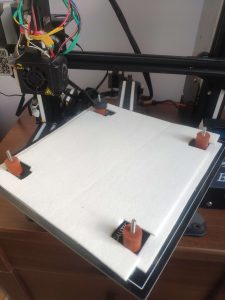
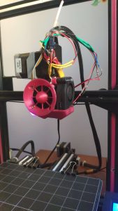
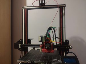
While waiting I upgraded the printer. I upgraded the print cooling fan to 5015 blower which improved the quality of overhangs greatly. I also changed the bed leveling springs with silicon ones, installed a isolation piece to keep the bed temperature stable. The leveling probe had a problem where it would trigger and drop mid print and damage itself. This was solved by adding a pull down resistor in its signal path. The whole process was a speed run for me to get into 3D printing and design.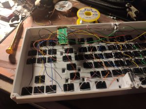
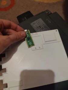
For wiring I did not really plan anything since it turns out you don’t really need to. Diodes are used to connect switches to rows and other pins of the switches are connected to columns. This was the micro controller can detect each key press with minimal amounts of pins. The micro controller in this case is Raspberry Pi Pico. It was selected over the Arduino Micro since it is cheaper, more powerful, and has more input/output pins. KMK keyboard software is used to make it work. Unfortunately I put the screw holes for the Pico on the bottom plate, so I had to get the wires longer in order for it to be possible to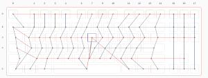 screw it while it is connected to the switches and close the back.
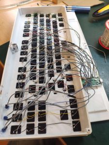
The matrix looks like the on on the right. The problem is that I forgot a switch in the middle. But that is easy to solve. Only thing needed is to put it to bottom row and connect it to one of the columns in the middle with missing bottom row switches. I ended up discovering that there was another switch I forgot to wire in the middle so I did the same thing. I also ended up fixing the shifted most left column since it made writing the code difficult. I will add the final matrix image when I get to my PC.
For anyone interested the key map has the be written by hand. Xs are empty switches in the matrix. And I t can be seen in my code that I put the U and 1 key at the bottom row. This required some experimentation to get it exactly right.
keyboard.keymap = [
[KC.ESC, KC.F1, KC.F2, KC.F3, KC.F4, KC.F5, KC.F6, KC.F7, KC.F8, KC.F9, KC.F10, KC.F11, KC.F12, KC.PSCR, KC.SLCK, KC.PAUS,
KC.ZKHK, KC.N2, KC.N3, KC.N4, KC.N5, KC.N6, KC.N7, KC.N8, KC.N9, KC.N0, KC.MINS, KC.EQL, KC.BSPC, KC.INS, KC.HOME, KC.PGUP,
KC.TAB, KC.Q, KC.W, KC.E, KC.R, KC.T, KC.Y, KC.I, KC.O, KC.P, KC.LBRC, KC.RBRC, KC.BSLS, KC.DEL, KC.END, KC.PGDN,
KC.CAPS, KC.A, KC.S, KC.D, KC.F, KC.G, KC.H, KC.J, KC.K, KC.L, KC.SCLN, KC.QUOT, KC.ENT, KC.NO, KC.NO, KC.NO,
KC.LSFT, XXXXXXX, KC.Z, KC.X, KC.C, KC.V, KC.B, KC.N, KC.M, KC.COMM, KC.DOT, KC.SLSH, KC.RSFT, XXXXXXX, KC.UP, XXXXXXX,
XXXXXXX, KC.LCTL, KC.RWIN, KC.LALT, XXXXXXX, KC.N1, KC.SPC, KC.U, XXXXXXX, XXXXXXX, KC.RWIN, KC.RALT, KC.RCTL, KC.LEFT, KC.DOWN, KC.RIGHT,
]
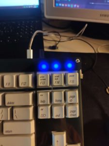
Most of the other required info can be found from GitHub page of KMK. I also added 3 blue LEDs for indicator lights for Caps Lock and Scroll Lock key. Since I couldn’t find a use case for the third it stays on for the time being. At this point it was fully ready and I was anxiously waiting for the key caps to arrive, hoping they would not get lost in customs.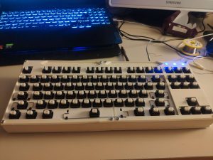
After my key caps arrived and I put them on unfortunately the front plate interfered with some of them, causing them to not be able to fully go down. This required making another front plate which was a good opportunity to get it cut with laser from acrylic since I was at school. I quickly got a .dxf file from my Solidworks model and after few tries I got it good enough with enough clearance for key caps to freely move.
While I am at it I also got the bottom piece from acrylic for added flatness since 3D prints weren’t exactly flat.
This black acrylic I found made the LEDs diffuse nicely as a added bonus.
I added some back lights after seeing that back piece is diffusing light very nicely as well. It is again bit flawed but it is hand made after all.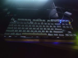
And that is it. Thanks if you read through it all. I wanted to write this as a detailed guide but I didn’t really documented the process and most of these photos are from my past discord chats. But I have all of the files needed to make this keyboard. I just can not upload them here. I may open a Thingiverse page for it later. Until that feel free to ask for them if you really want to build it.