IVUS – CT Registration
- Abstract
In this work, we present a method for correlating the intravascular ultrasound(IVUS) frames with the 3D coronary vessel model extracted from the Computer Tomography(CT). This step is helpful for the cardiologists in surgery planning, stent placement and diagnosis. The cardiologists can determine the exact position of the thinned vessel or the part of the vessel which contains dangereous plaques with the method, thus make a better diagnosis and determine a more accurate position of the stent that will be placed and plan the surgery more easily.
Here, we aim to find the corresponding 3D positions of each IVUS frame by matching the selected features chosen from the 3D model and IVUS pullback.
- Steps
1. Coronary Vessel Segmentation in CT
For the 3D model of the coronary vessels, we use external software which constructs a 3D model from the binary vessel segmentation that is extracted from CT data and saves in STL(stereolithography) file format.
2. Centerline Extraction
During the pullback, the IVUS catheter follows a path inside the artery vessel that is subject to pullback acquisition. In this first version of the work, we assume that the catheter follows the centerlines of the coronary vessel.
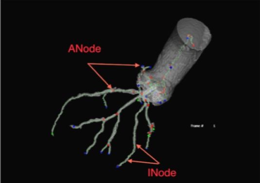
The centerlines are represented as a graph, consisting of two different node types: Anode and Inode. Anode’s are the main nodes of the graph and Inodes are created between the two Anodes as sampling nodes for the sake of visualization and ease of implementation. [implemented by Dr. Martin Groher]
3. Feature Selection
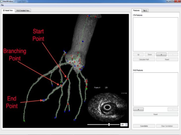
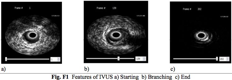
Three main features can be mentioned that is visible both in IVUS and 3D model of the coronary vessels.(See below)
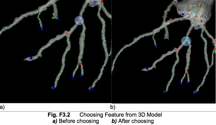
Features can also be chosen manually.
4. Shortest Path Calculation
The shortest path that is passing through the chosen nodes is calculated with depth first search algorithm on the graph.
5. Correlation
Correlation is made, based on the distances in both modalites. The total distance of the path in the 3D model is calculated after finding the shortest path between the chosen features and the total distance of the pullback in IVUS is described as the number of frames between the first selected feature and the last selected feature. After that the ratio between the total distances is calculated, the nodes corresponding to each IVUS frame is found by finding the distance scope of each IVUS frame and assigning the nodes between that distance scope.
- Acknowledgements
This software was developed C++, Qt and VTK in Summer 2010 in TU Munich by Gozde Gul Isguder (Sabanci University- Masters Student). This project is financially supported by Tubitak (via Ass. Prof. Dr. Gozde Unal). Centerline extraction algorithm is provided by Dr. Martin Groher(TUM).


